Although the speed of the fiber laser cutting machine is very high. There are still rooms for improving its cutting efficiency by proper using of its functions. There are 6 practical processes which can greatly improve the cutting efficiency of the fiber laser cutting machine.
Table of Contents
Leapfrog
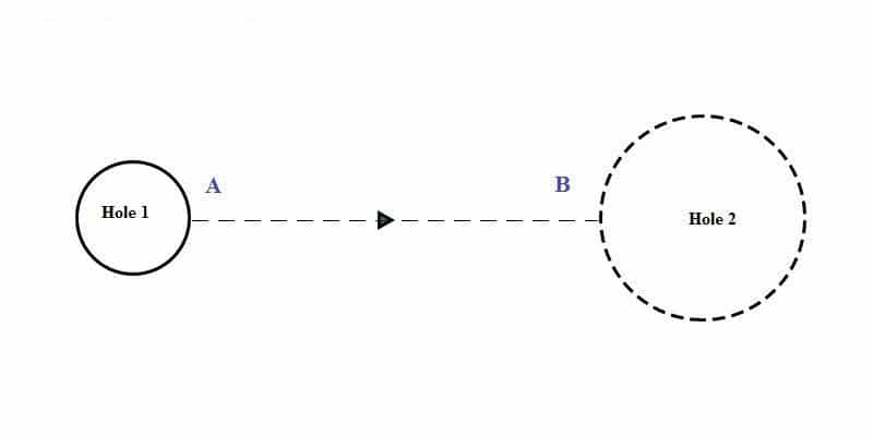
As the name suggests, the leapfrog is like a frog jumping. It is the idle stroke mode of fiber laser cutting machine As shown in the figure below when finishing cutting hole 1 to cut hole 2, the cutting head is moved from point A to point B. Sure, the laser should be turned off during the movement. From point A to point B, the machine runs “idly ” and is called idle stroke.
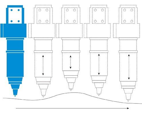
The path of the laser cutting machine in the early stage is shown in the figure below. The cutting head completes three actions in a row: rising (to a safe enough height), parallel moving (above the point B), and descending.
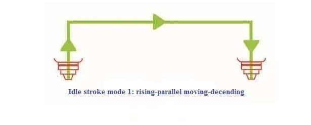
The efficiency of the fiber laser cutting machine can be increased by cutting the idle time. If the three completed actions in a row are completed “simultaneously”, the idle time can be shortened: when moving from point A to point B, the cutting head rises at the same time; when it approaches point B, it drops simultaneously. As is shown below.
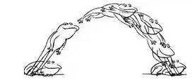
The trace of the cutting head’s idle motion is like an arc drawn by a frog jumping. In the development of laser cutting machines, the leapfrog is considered to be a prominent technological advancement. The leapfrog movement only takes up the time from point A to point B, saving time for ascending and descending. Like the frog jumped and caught the food; the leapfrog of the fiber laser cutting machine “captured” the high efficiency. If not with the leapfrog function, the fiber laser cutting machine lags behind the trend.
Bridge (Micro-joint)
When the laser cutting process is performed, the sheet is supported by a zigzag support strip. The cut-out parts, if not small enough, cannot fall from the gaps of the support strips; if they are not large enough to be supported by the support strips, they may lose balance and even lift. The high-speed moving cutting head may collide with it, resulting in stopping the machine, or damage the cutting head.
This phenomenon can be avoided by using the bridge (micro-join) cutting process. When laser cutting the board is programmed, the closed contour can be broken several places, so that after the cutting is completed, the parts are stuck with the surrounding materials and will not fall. These breaks are bridges, also called breakpoints, or micro-joint, as shown in Figure 4. The breaking distance is generally 0.2 to 1 mm, which is inversely proportional to the thickness of the sheet.
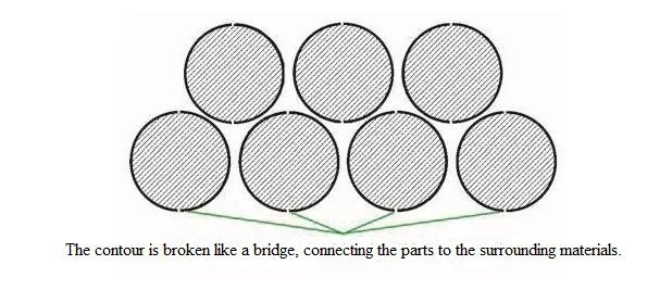
The bridge connects the part to the surrounding material, and the sophisticated programming software automatically adds the appropriate number of bridges depending on the length of the profile. It is also possible to distinguish between the inner and outer contours and decide whether to increase the bridge position so that the inner contour (waste) of the bridge is not dropped, and the outer contour (part) of the bridge position is adhered to the base material without falling, thereby eliminating the need to Sorting work.
Automatic Focusing
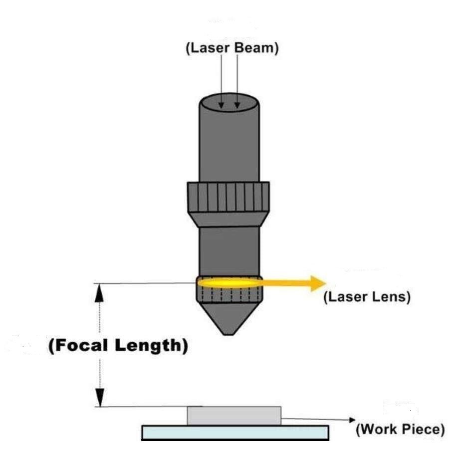
When laser cutting machines are used for sheet metal cutting, the first step is to set the focus on the surface of the sheet. Depending on the material being cut, the corresponding required laser focus position will be different. As is shown below.
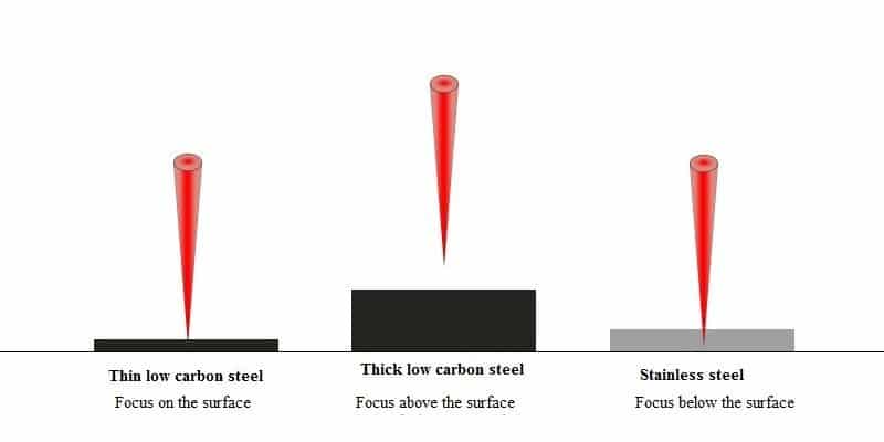
The earliest laser cutting machines were generally manual focusing, but due to the many preconditions required for manual focusing, the focusing process was cumbersome; later it was slowly upgraded to an autofocus laser head.
Some people think that as long as the height of the cutting head is changed, the cutting head is raised, the focus position is raised, the cutting head is lowered, and the focus position is lowered. In fact, it is not that simple. As is known, the bottom of the cutting head is a nozzle. During the cutting process, the distance between the nozzle and the workpiece (nozzle height) is about 0.5 to 1.5 mm, which is a fixed value, that is, the nozzle height is constant, so the focus cannot be adjusted by lifting the cutting head. Otherwise, the cutting process cannot be completed.
The focal length of the focusing mirror is immutable, so it is not possible to adjust the focus by changing the focal length either. By changing the position of the focusing mirror, the focus position can be changed: when the focusing mirror is lowered, the focus is lowered; when the focusing mirror is raised, the focus is raised. This is a way of auto-focusing, which requires the motor to drive the focusing mirror to move up and down to achieve auto-focusing.
Another method of autofocusing is to configure a variable curvature mirror (or tunable mirror) before the beam enters the focusing mirror, and change the divergence angle of the reflected beam by changing the curvature of the mirror, thereby changing the focus position (Figure 6).
-
Figure 6 Auto focusing 1 -
Figure 6 Auto focusing 2
With the automatic focusing function, the processing efficiency of the laser cutting machine can be significantly improved: the perforation time of the thick plate is greatly reduced; the workpiece can be quickly adjusted to the most suitable position by processing workpieces of different materials and thicknesses.
Concentrated Perforation
Concentrated perforation, also known as pre-perforation, is a processing technique that is not a function of the laser cutting machine itself. When laser cutting thicker plates, the cutting process of each contour has to go through two stages, one is perforation and the other is cutting.
The conventional processing technology is: A point perforation → cutting contour 1 → B point perforation → cutting contour 2 →… The so-called concentrated perforation is to concentrate all the perforation processes on the whole plate in advance, and then go back to perform the cutting process. The centralized perforation process is: complete the perforation of all contours → return to the starting point → cut all contours, as shown in Figure 7.
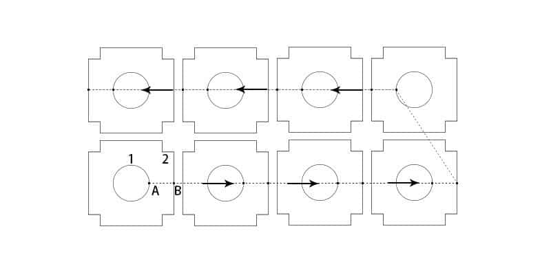
Compared to conventional machining processes, the total length of the machine’s trajectory is increased when the perforation is concentrated. However, this processing can avoid the occurrence of over-burning. During the perforation of the thick plate, heat is formed around the perforation point, and if it is followed by cutting, a burn phenomenon occurs. By adopting the centralized perforation process, when all the perforations are completed and the starting point is re-cut, the over-burning phenomenon is avoided due to sufficient time for heat dissipation.
Concentrated perforation is also a risk. If a collision occurs during the cutting process, causing the position of the sheet to change, the portion that has not been cut may be scrapped. The application of the centralized perforation process requires the use of an automated programming system.
Common Edge Cutting
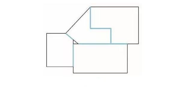
If the contours of the adjacent parts to be cut are straight and the angles are the same, then they can be combined into one straight line, and only one cut is the common edge cutting. Co-edge cutting reduces the length of the cut and reduces the number of perforations, which can significantly improve efficiency.
As shown in the figure below, the red side is the common edge and can be cut side by side.
Advantages of co-edge cutting:
Reduce processing time
Minimize material waste
Save cutting gas
Reduce wear on machine parts
Common edge cutting is available for the following parts:
Contour with a long straight edge
Low-speed thick slab cutting
An entity that needs to be sprayed twice.
Automatic Edge-seeking
When the sheet is placed on the worktable, if the sheet is skewed, it may cause waste when cutting. If the metal laser cutting machine can sense the angle and origin of the sheet tilt, the cutting process can be adjusted to suit the angle and position of the sheet to avoid waste.
When the automatic edge finding function is started, the cutting head starts from the P point and automatically measures 3 points on the two vertical sides of the sheet: P1, P2, P3, and automatically calculates the inclination angle A of the sheet as well as the origin of sheet material. As is shown in Figure 9.
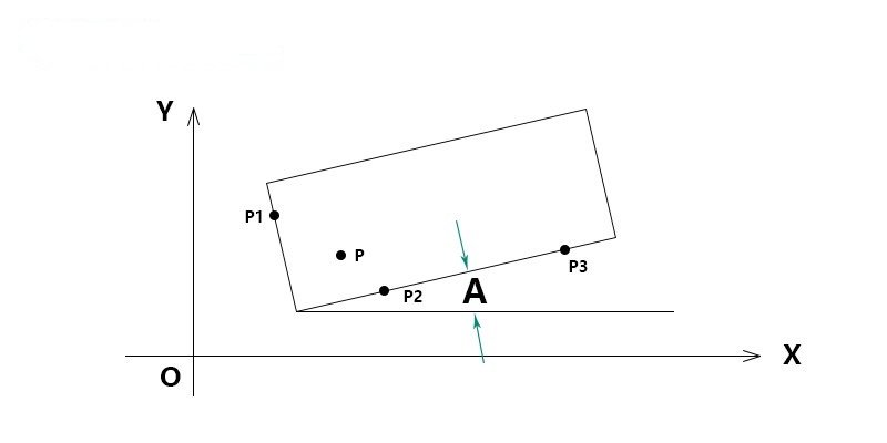
With the automatic edge finding function, the time to adjust the workpiece is reduced, the work intensity is reduced, and the cutting efficiency is improved.

